The Chenile STM supports the definition of custom Domain Specific Languages (DSL). DSLs enable expressiveness. It is possible to figure out the intent of the State Transition Diagram (STD) without elaborate explanations.
First, let us consider a simple manufacturing process as illustrated in the test case below:
Please see Java Test code and XML file for the test code and XML files.
We consider a product that is being manufactured using an assembly line. As discussed in the comments in the XML file here are the major steps:
- INITIATED
- IN_ASSEMBLY_LINE
- OUT_OF_ASSEMBLY_LINE
- READY
- SOLD
Here is a State diagram that is generated by the Chenile State Machine (STM) for the XML file:
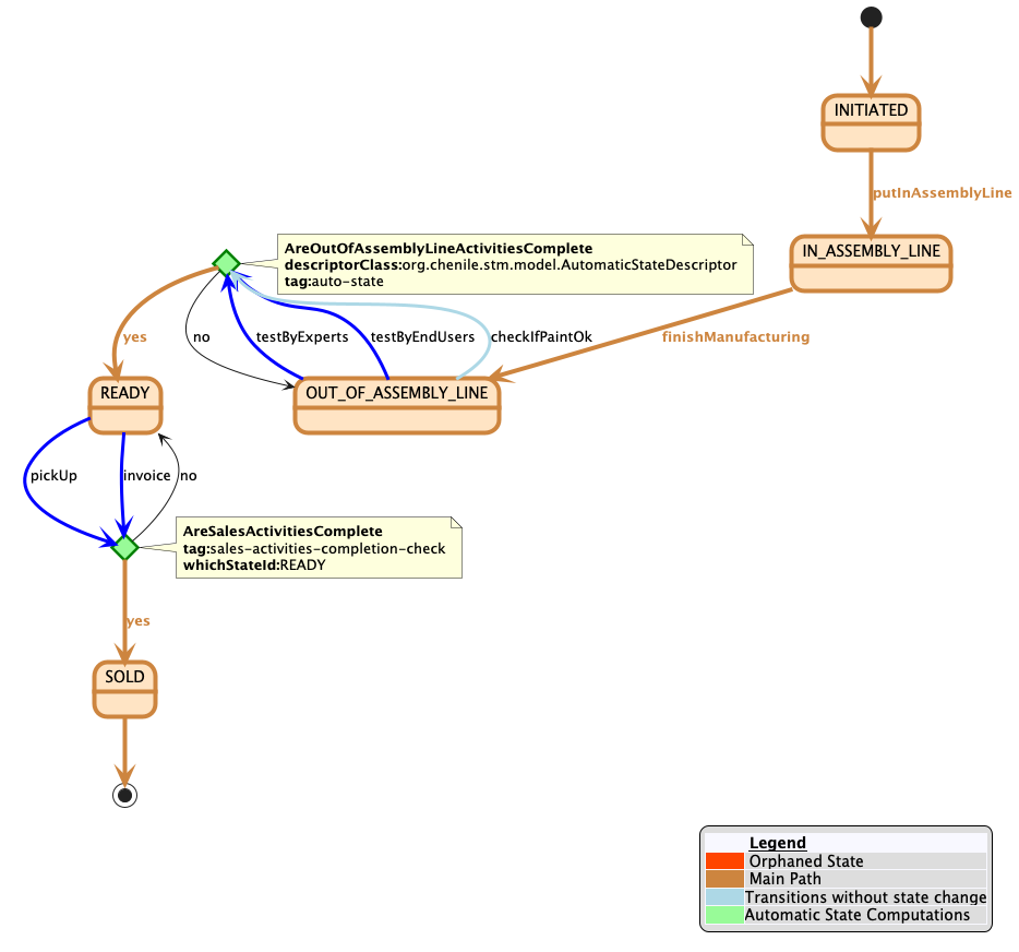
The state diagram clearly shows the main path that should be taken in the life cycle of the product. It also shows the activities that need to be performed at various places.
How to define the state machine
In this case, it is best to define the States xml. Here is a first cut at defining the states.
<states>
	<!-- preliminary definitions -->
	<flow id='MFG_FLOW' default='true'>

		<manual-state id="INITIATED" meta-mainPath="true" INITIALSTATE="true">
			<on eventId="putInAssemblyLine" newStateId="IN_ASSEMBLY_LINE"/>
		</manual-state>

		<manual-state id='IN_ASSEMBLY_LINE'>
			<on eventId="finishManufacturing" newStateId="OUT_OF_ASSEMBLY_LINE"/>
		</manual-state>
		<stage id='OUT_OF_ASSEMBLY_LINE'>
			<mandatory-ooa-activity id="testByExperts" />
			<mandatory-ooa-activity id="testByEndUsers" />
			<optional-ooa-activity  id="checkIfPaintOk" />
		</stage>
		<auto-state id="AreOutOfAssemblyLineActivitiesComplete"
					componentName="areOutOfAssemblyLineActivitiesComplete" >
			<if-not-complete stay-in="OUT_OF_ASSEMBLY_LINE"/>
			<on-completion goto="READY"/>
		</auto-state>
		<stage id="READY" >
			<mandatory-sales-activity id="invoice"/>
			<mandatory-sales-activity id="pickUp"/>
		</stage>
		<sales-activities-completion-check >
			<if-not-complete stay-in="READY"/>
			<on-completion goto="SOLD"/>
		</sales-activities-completion-check>
		<stage id="SOLD"/>
	</flow>
</states>